
Page 20 - Index
P. 20
increased negative tail lift as SISO. The aircraft in longitu-
is needed to maintain the dinal and pitching motion may
trimmed flight condition be modeled using a state-space
and prevent the aircraft from model. The longitudinal aircraft
tending to nose down and dynamics are linearized around
overspeed with flaps extended. the setpoint (airspeed and pitch)
This is achieved by increasing and can be written in state-
elevator trailing edge to com- space form:
pensate (see Figure 4). X=A long X+B long u Equation 1
When flaps are retracted The elements of Matrix A are
(see Figure 4), the lift generat- stability derivatives describing
ed by the wing decreases and the effect of state variables
the point of lift moves forward. on forces and moments. The
The aircraft tends to nose up elements of Matrix B are control
as the nose-down pitching derivatives representing the
moment decreases due to wing effects of elevator and throttle
lift. Increased trailing edge commands on the body refer-
down elevator is required to enced forces and moments.
compensate. At the tailplane,
Figure 3. Contributions to total aircraft pitching moment around the downwash angle decreas- Transfer Functions, Elevator
the center of gravity. es therefore negative tail lift
decreases. The aircraft tends to Pitch
to nose down as the pitching Using this matrix method,
moment decreases due to transfer functions (input-output
negative tail lift. This time, relationships) can be derived
increased trailing edge up using the desktop computing
elevator is required to com- mathematical modeling tool
pensate. The resultant pitching Matlab to determine the rela-
moment around the center of tionship between input: elevator
gravity is the net effect of these deflection (η) and output: pitch
contributions. The effects due angle (θ).
to tailplane are usually domi-
nant (see Figure 5). Effects of Flap Retraction
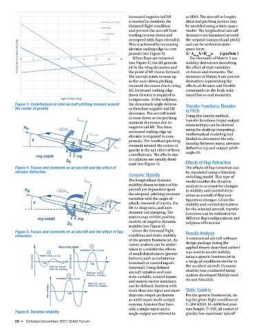
Figure 4. Forces and moments on an aircraft and the effect of The effects of flap retraction can
elevator deflection. be simulated using a Simulink
Dynamic Stability switching model. This type of
The longitudinal dynamic model enables the dynamic
stability characteristics of the analysis to account for changes
aircraft are dependent upon in stability and control deriv-
the airspeed, pitching moment atives as a result of flap con-
variation with the angle of figuration changes. Given the
attack, moment of inertia, the stability and control derivatives
lift-to-drag ratio, and aero- for the selected aircraft, transfer
dynamic tail damping. The functions can be estimated for
system may exhibit positive, different flap configurations and
neutral, or negative dynamic tailplane efficiencies.
stability (see Figure 6).
Figure 5. Forces and moments on an aircraft and the effect of flap Given the trimmed flight Results Analysis
retraction. condition and static stability
of the generic business jet, dy- A commercial aircraft software
namic analysis can be under- design package (using the
taken to consider the effects applied theory described earlier)
of small disturbances (pertur- was used to model stability
bations) such as turbulence using a generic business jet in
(external) or control inputs a range of conditions similar to
(internal). Using defined the accident aircraft. Dynamic
aircraft notation and axes analysis was conducted using
state variable, control inputs custom-developed Matlab mod-
and matrix/vector notations els and Simulink.
can be defined. Systems with
more than one input and more Static Stability
than one output are known For the generic business jet, us-
as multi-input multi-output ing the given flight condition of
systems. Systems that have V=204 KTAS, H=4,000 feet pres-
only a single-input and a sure height, T=29F, aft center of
Figure 6. Dynamic stability. single-output are referred to gravity/low maximum takeoff
20 • October-December 2021 ISASI Forum