Page 11 - Forum-2021-JanToMarch
P. 11

proximates the position
                                                                                               of one position of the
                                                                                               observed object as shown
                                                                                               in the right image. In this
                                                                                               case, the B-767’s position
                                                                                               (intersection of both lines
                                                                                               of sight) was located,
                                                                                               considering the potential
                                                                                               errors.
                                                                                                 The images in Figure 8
                                                                                               show one single frame of
        Figure 9. Attitude error +/-10 degrees visualized (blue/cyan), heading (left), pitch (middle), roll (right).  the video. The left image
                                                                                               shows the outline of the
                                                                                               aircraft behind trees. To
                                                                                               determine the attitude of
                                                                                               the aicraft, a 3-D model
                                                                                               of a B-767 was placed in
                                                                                               the 3-D software applica-
                                                                                               tion at the reconstructed
                                                                                               position and the attitudes
                                                                                               of the aircraft such as
                                                                                               heading, pitch, and roll
                                                                                               were adjusted until the
                                                                                               objects fitted best to the
                                                                                               outline in the image. The
                                                                                               accuracy for attitude
                                                                                               reconstruction depends
                                                                                               on the resolution of the
                                                                                               frame. However the
                                                                                               potential error can be up
                                                                                               to +/- 10 degrees based on
                                                                                               experience.
                                                                                                 To better explain the
                                                                                               reason for the experi-
                                                                                               enced size of the error in
                                                                                               attitude, Figure 9 shows
                                                                                               the visual differences.
                                                                                               The modified values for
                                                                                               +/-10 degrees are visu-
                                                                                               alized in blue and cyan
                                                                                               and overlayed. Based on
        Figure 10. Illustration of the reconstructed flight path with error tunnel (white circles) that shows the
        line of sight from the first observing camera (light blue) and second observing camera (dark blue).   the experience of several
                                                                                               reconstructions and video
                                                                                               data, a good fit could be
                                                                                               determined within the
                                                                                               maximum error of +/-10
                                                                                               degrees for all three axis.
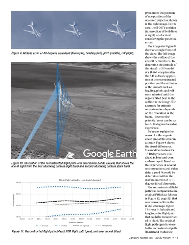
                                                                                                 The reconstructed flight
                                                                                               path was compared to the
                                                                                               original FDR data (shown
                                                                                               in Figure 12, page 12) that
                                                                                               was recovered from the
                                                                                               B-767 wreckage. Figure
                                                                                               11 shows in latitude and
                                                                                               longitude the flight path
                                                                                               that could be reconstruct-
                                                                                               ed in black. The original
                                                                                               flight path (grey) is close
                                                                                               to the reconstructed path
         Figure 11. Reconstructed flight path (black), FDR flight path (grey), and error tunnel (blue).  (black) and within the
                                                                                     January-March 2021 ISASI Forum  •  11
   6   7   8   9   10   11   12   13   14   15   16